article
Increasing energy efficiency in pneumatic conveying systems
Pneumatic conveying is a clean, quick and reliable way of moving materials around the plant and is almost always the most efficient means of transporting materials around a site. In those instances where pneumatic conveying does not look like an efficient option, the reason is typically given as high energy consumption. However, the introduction of a new rotary airlock, the V-Series Feeder / Airlock, reduces the installed power of pneumatic conveying systems and lowers operating costs significantly.

Ideal for both fine and coarse-grained materials, pneumatic conveying lines can be installed almost anywhere they are needed around cement plants and terminals – with much greater flexibility in terms of layout than their mechanical alternatives. High, low, bending left or right, they can adapt to your needs, enabling you to fit a new line into even the busiest sites. The enclosed pipe ensures no dust escapes to the local environment, keeping your plant clean and reducing the maintenance burden that comes from contaminants getting into machinery. The maintenance needs of the systems themselves are also low because there are very few moving parts, which gives you excellent availability as well as maximum peace of mind. And the capacity to convey at high pressures ensures you have ample throughput to meet the demands of your process.
All this adds up to a very low total cost of ownership compared with mechanical conveying, where the maintenance needs and associated productivity losses are much higher, and the flexibility is much lower. The result is that pneumatic conveying is almost always the most efficient means of transporting materials around a site.
In those instances where pneumatic conveying does not look like an efficient option, the reason is typically given as high energy consumption. However, the introduction of a new rotary airlock, the V-Series Airlock/Feeder, reduces the installed power of pneumatic conveying systems and lowers operating costs significantly.
Case study 1: Kiln feed system with screw pump option
Historically, the screw pump has been the preferred means of feeding pneumatic conveying lines. With more than 100 years’ experience, it is a proven technology and one that is still highly applicable for many conveying applications transporting fine, dry materials. But while the system is flexible in terms of capacity and layout, it can be beaten on energy efficiency by a rotary airlock. The following case studies illustrate two such examples.
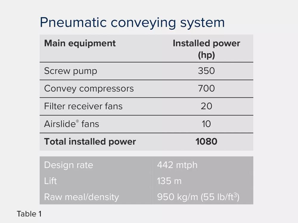
Table 1 shows the details of the energy requirement for a cement plant’s pneumatic conveying system with screw pump. This particular plant was using a pneumatic conveying system to transport raw meal to the preheater tower. To reduce the energy load for this operation, the plant wanted to explore alternatives to the screw pump line charger. We introduced them to the new V-Series rotary airlock.
Case study 1: Kiln feed system with V-Series rotary airlock option
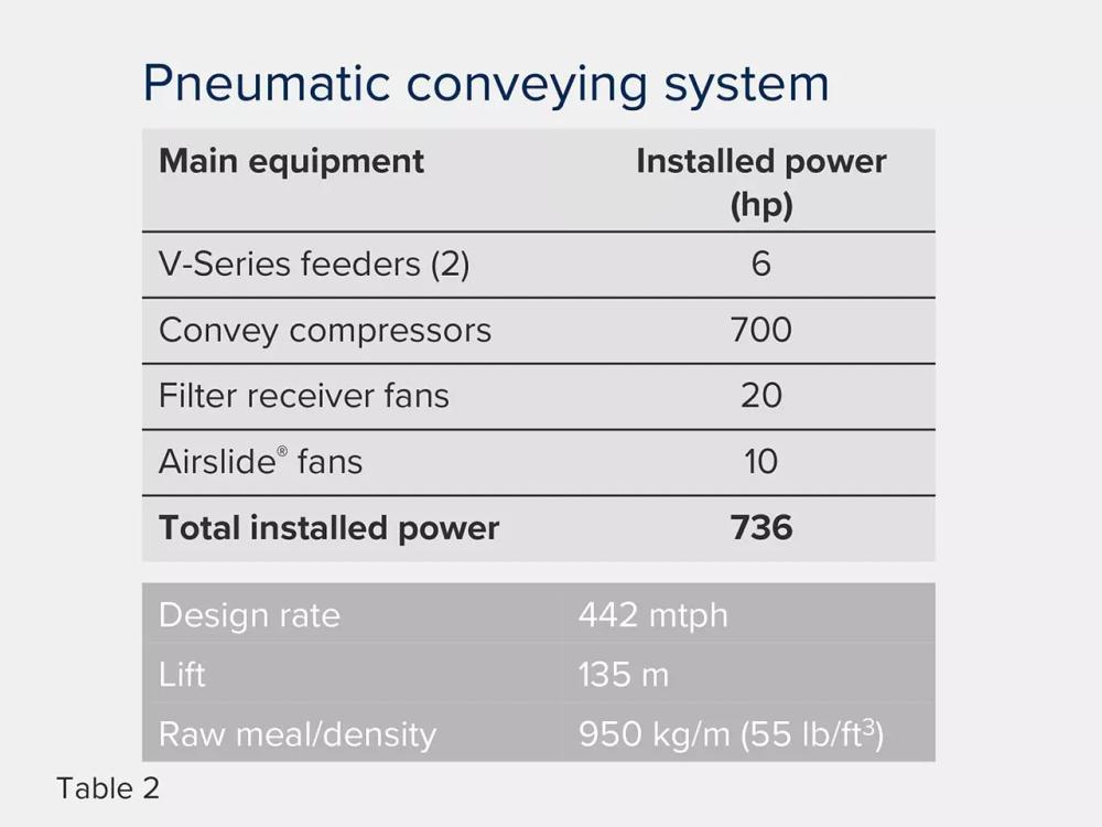
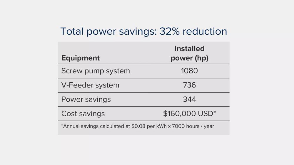
Table 2 shows the significant reduction in installed power required with the V-Series at just 6 hp compared with 350 hp for the screw pump. This was the energy requirement for two airlocks, as were needed in this case, with each having an installed power of just 3 hp. This translates to an overall savings in total installed power of 32% for the entire system and a reduction in operating costs of US$160 000 (Table 3, below), giving the plant a swift ROI of less than one year.
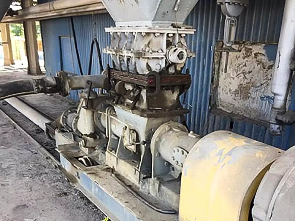
Case study 2: Replace a screw pump at a Cement terminal
The image on below shows an old screw pump at a cement terminal in the US. The terminal operators wanted to repurpose the old silos for red masonry cement, which they needed to store separately to prevent product contamination. They requested that we put in a system that replaced the old screw pump but maintained the existing 12 in. x 24 in. rotary cut-off valve shown in the picture. The role of the airlock was to discharge masonry cement from the silo to a packing bin at a rate of 50 stph in an 8 in. pipeline, measuring 200 ft. long with five 90˚ elbows.
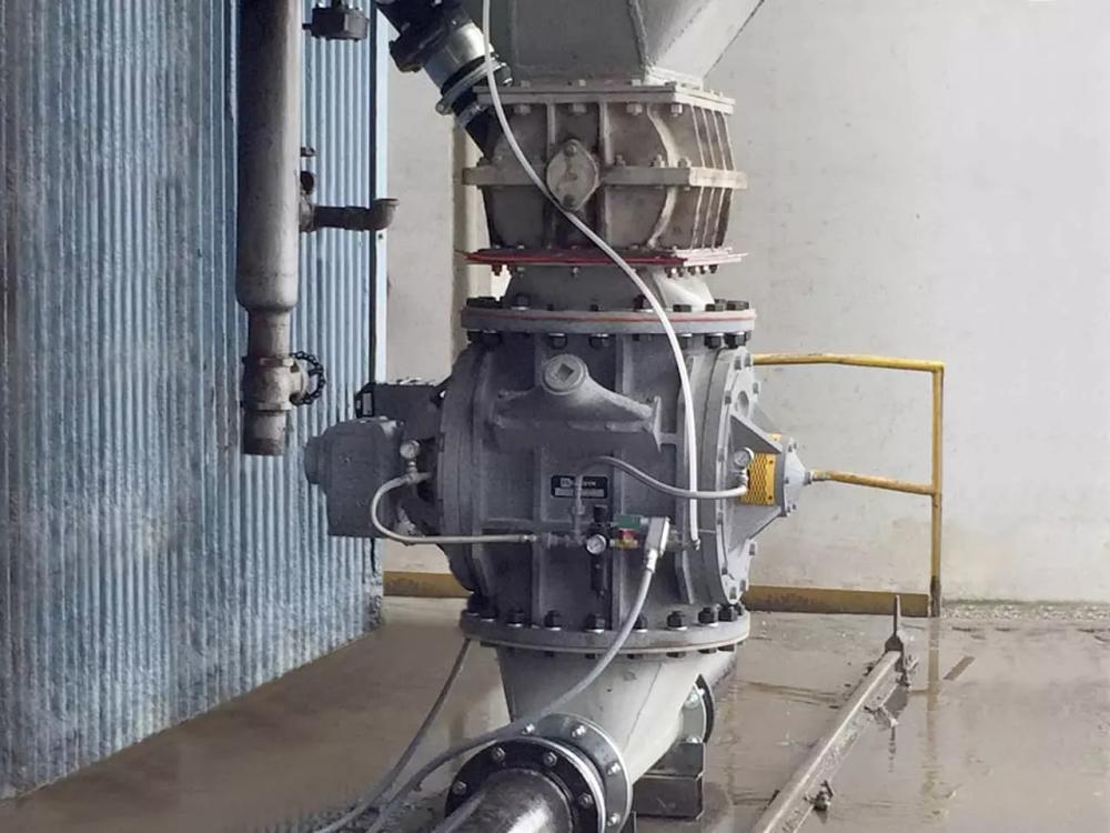
Case Study 2: New V-Series feeder system
The system we designed is shown below. We successfully installed the new V-Series feeder / airlock within the allotted space and achieved the desired capacity. The new system runs at 12 rpm, using the same air supply, which was 1400 sfcm at 18 psig. The feeder / airlock is installed with a variable speed drive set to operate at between 5 and 30 rpm using a VFD drive, giving the terminal operators optimum efficiency.
This installation proves the flexibility of the system, which can be retrofitted into small spaces and replace outdated technology.
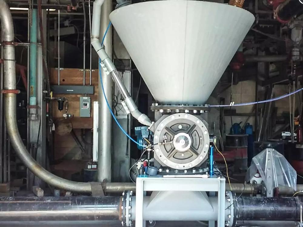
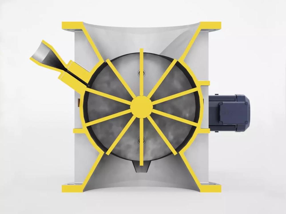
V-Series rotary airlock
The V-Series is a 10-vein rotary feeder / airlock designed to handle dry, fine powder or granular product at high-pressure differentials up to 29 psig (2 bar) in dense phase or dilute phase systems. It requires much less power on the drive motor, generating a significant energy saving, and it is more flexible in terms of the materials it can handle, giving plants the ability to transport a wider range of materials. In cement plants, the V-Series is typically used to transport cement kiln dust, cement, fly ash, pulverized coal and petcoke. In cement terminals, applications include unloading from railcars to storage silos, discharge from storage silos to use bins, loadout and packing systems.
Abrasion
Abrasive wear is a concern when operating rotary feeder / airlocks handling abrasive materials. Conventional feeder/airlocks are limited to lower pressure operation. However, this can be counteracted by the use of specialist ceramic and tungsten carbide coatings on the rotor and feeder veins with the V-series feeder/airlock, which allows us to handle more abrasive materials at higher pressures.
Upgrading old systems
In the case of the cement terminal, switching from a screw pump to an airlock brought about greater efficiency – and this is often the case for this kind of upgrade. However, it should be noted that in some instances when converting an old screw pump system to a rotary airlock, efficiency can be lost if displaced air needs to be compensated by increasing horsepower to the compressor or blower to an extent that the power savings on the airlock are cancelled out. For this reason, it’s essential to check the existing system thoroughly before assuming that an upgrade will result in energy savings.
How does pneumatic conveying work?
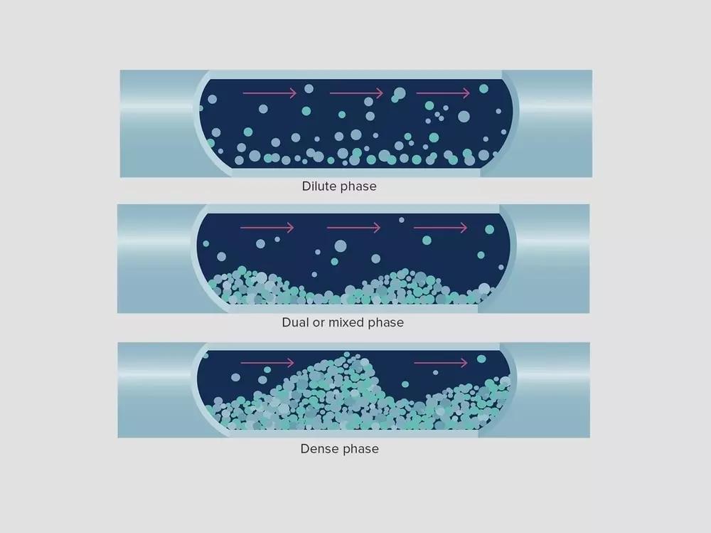
A typical pneumatic conveying system runs what is known as two-phase conveying. This is a mix of dense and dilute phase conveying, in which the pipe is more or less divided into a top half and a bottom half. Along the bottom, materials move relatively slowly. This is the dense phase. Along the top, you have fewer materials more widely dispersed in the dilute phase. These particles have been picked up by the conveying air and are almost flying along at a high velocity. As they lose velocity, they will drop out of the dilute phase and join the dense phase below. But, as the materials accumulate along the bottom of the pipe, the cross-sectional area through which air can move narrows and velocity increases again, allowing the conveying air to pick up particles and move them along at high velocity. This cycle repeats, giving a kind of wave formation in the materials along the bottom of the pipe.